|
RIMS AND VALVES |
| Valves |
|
Wheels/Rims |
|
Trelleborg Wheel Systems manufactures its own wheels
and has a wide range of high quality rims.
|
|
Wheel |
|
The rim for a TWIN wheel is a one piece design and rolled
with a profile to allow mounting of the tyre in the best possible way. |
 |
|
Rim types |
|
There are two existing main types of rim related to tyre
bead seat angle.
|
 |
|
Rim types can be identified by the rim diameter.
|
 |
|
Hump rim |
|
Hump is a raised profile on the tyre bead seat, which
holds the tyre firmely in place on its bead seat, even at low pressure. |
 |
|
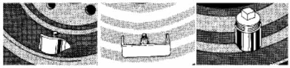
Rim edge reinforcement |
|
TWIN wheels used for forestry and construction machines are often exposed to large mechanical stress and therefore the rim flanges need reinforcements. There are two different reinforcements: box type and round iron type.
|
 Box type reinforcement Round iron reinforcement |
|
Valve guards |
|
TWIN rim can be equipped with different types of airvalve
guards:
|
|
|
Rim size |
|
Measurements are always given in inches e.g. 16.00x22.5”
and DW20Ax34”.
|
|
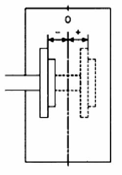
Rim offset |
|
Rim offset states the position for the disc hub contact
surface related to the rim centreline.
|
 |
|
Hole pattern/Marking-Disc |
|
To make it possible to fit a wheel on a hub, the disc
must have a hole pattern matched to the wheel bolts and hub configuration. |
 |
|
|
|
|
|
Painting |
|
All TWIN wheel rims are painted with a powder coating, giving a very high finish and durability. The wheels can be delivered in following basic colors: silver, white, red, yellow (construction type) ands yellow (John Deere type) as well as other special colors.
|